

 The circular runout symbol is used to control the radial deviations of any given cross-sectional elements of a circular feature. The radial deviations are taken with respect to an axis of rotation established by the referenced datum feature.
Circular Runout Symbol and Callout
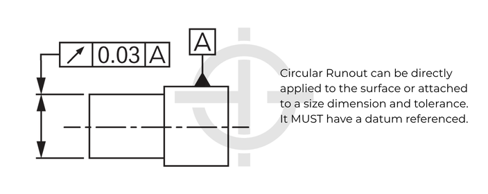
Functionally speaking, runout is controlling how much one feature can vary with respect to another feature (identified as a datum) when the part is rotated 360° around the datum axis. It is essentially a control of a circular feature and how much variation its surface can have with respect to the rotational axis. Runout can be called out on any feature that has circular cross sections that are centered about an axis, meaning it can be applied to conical and cylindrical features as well as curved surfaces. It is essentially how much “wobble” occurs in any given cross section of that feature as it rotates around an axis.
Circular Runout Tolerance Zone
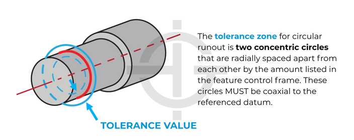
The tolerance zone is two concentric circles, one inner and one outer, that are coaxial to the datum axis. All of the cross-sectional surface elements must fall within the zone. The tolerance zone lies on a plane that is perpendicular to the datum axis. The value of the feature control frame for the circular runout tolerance is the radial distance between the two concentric circles that establish the tolerance zone. Another way to view circular runout is the difference between the smallest and largest radial distances any surface elements have with respect to the datum axis.
How to Inspect Circular Runout
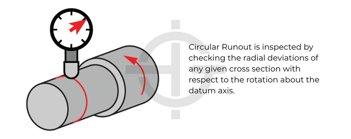
Runout is measured by using a simple indicator that is placed on the surface of the feature. For drop indicators it’s important to ensure the indicator is normal to the surface and perpendicular to the axis of rotation. The datum axis is created by engaging all surface elements of the datum feature and rotating about this datum feature. The axis of rotation creates the datum axis. The axis of rotation can be created by using V-Blocks, a collet or chucks on a lathe or even bench centers. The part is then rotated around this axis, and the variation is measured using the height gage held perpendicular to the part surface. If the gage does not vary by more than the runout tolerance, the part is in spec. Remember, multiple cross sections must be checked since the control applies to the entire surface.
We cover the intricacies of circular runout, how it’s interpreted, how its inspected and the miscellaneous things you should know about this symbol in our GD&T Fundamentals Course as well as our GD&T Inspection Course. These courses show you everything you need to know about circular runout and then some!
Example and When to Use Circular Runout
Runout and its 3D cousin, Total runout, are very common symbols in GD&T due to the control they have on a rotating part. They are used in any rotating components such as drills, gears, shafts, axles, and many machine tool parts. The automotive and industrial industry uses this GD&T symbol very often on any part that is rotated. Runout usually is put into place when oscillations or vibrations need to be controlled on a fast rotating part, like an engine or transmission. If the part rotates it probably requires runout.
Example:
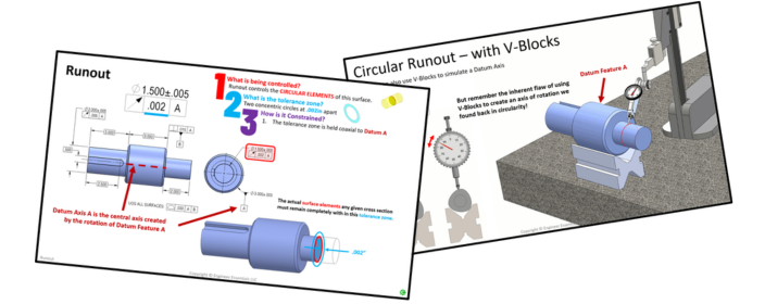
A shaft that is rotated at very high speeds is prone to oscillations if the right edge of the shaft is too far offset from the center cylinder. To control how much wobble this part will have, runout is used to ensure that the smaller diameter surface is controlled relative to datum feature A.
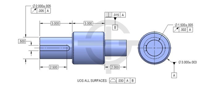
To control this without Geometric Dimensioning and Tolerancing would be nearly impossible. The small amount of variation in the shaft, straightness of the shaft, and roundness of the individual cross sections would be unrealistic to control. With runout, you have your final rotational condition that you want controlled without needing to specify unnecessary tight control on the entire part.
By constraining with runout as shown on the drawing, you are ensuring that when the shaft is rotating around datum feature A, the surface being controlled will not vary in surface deviations more than 2 thousands of an inch. This will ensure that only a limited vibration is made and that both parts will wear evenly. To ensure this condition is met, you must measure the parts with a gage.
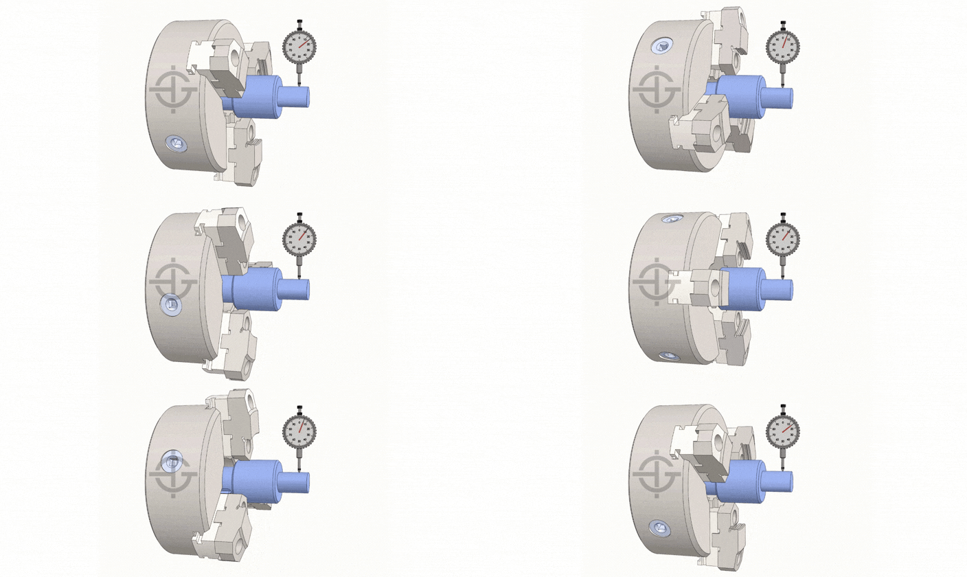
Note: Gage cannot deviate more than two thousandths. This runout must be checked on any cross-section along the referenced surface. You must gage each cross-section separately though (Gaging the entire cylinder in one recorded deviation at once would be total runout).
Circular Runout vs. Total Runout
Runout is the 2D version of total runout. While it is measured in individual cross-sections, total runout takes the measurement around and across the surface of the entire part in a 3D tolerance zone.
Circular runout can be applied to spherical, conical, and irregular surfaces that rotate around an axis of rotation while total runout can only be applied to straight surface elements such as cylindrical, conical, and flat planar surfaces (that are perpendicular to the datum axis).
Additionally, circular runout will NOT control the amount of taper a cylinder can have, that would be left up to the tolerance of size for that feature. Whereas if Total Runout were applied, this tolerance WOULD restrict the amount of taper a cylinder could have to its tolerance listed in the feature control frame.

All Symbols





































I am designing a shear shaft that requires the splines on each end to be coaxial. Can the datum be determined by the pitch diameter of the splines or does the datum need to be solid cylindrical surface? Is it best to use concentricity over runout for these parts?
Sue –
Ugh, avoid using concentricity if you can. It’s incredibly difficult to machine to and equally as difficult to inspect (read this as $$$). Furthermore, you can effectively achieve similar control by using the other controls. As far as specifying a datum around the spline, you can use the concept of an irregular feature of size to control it and if you create a datum from it you need to specify whether you are applying it to the major, minor or pitch diameter.
Hope this helps. Cheers,
Matt
I have a question. When I read the ASME Y14.5 standard, I found a fig. 3-29 (page47). That fig showed datum B was constrained by runout referring to datum A and datum C. I don’t know how to understand runout referring to datum A.
Mark –
For runout controls, the datum axis (per 9.3.1 pg. 180) may be established in one of 3 ways.
1. A cylindrical datum feature of sufficient length
2. Two or more cylindrical datum features having sufficient axial separation
3. A cylindrical datum feature and a face at right angles to it
In the case of Fig 3-29, the designer determined that datum C did NOT have sufficient length. The point behind stating sufficient length is for stability. A good rule of thumb is that the length of your datum axis needs to be at least as long as the diameter of the feature you are trying to control. It’s somewhat relative though and left up to the designer’s judgement.
I’ll refer you to Figure 9-5 on page 183 that uses another example of a stubby cylindrical datum feature and a flat surface perpendicular to it. The flat face is helping to orient the part in a set of jaws or mandrel to prevent lobing when you try to rotate it for measurement.
I hope this helps clarify things for you. Please come back and comment in the future.
Cheers,
Matt
Sir
I am working on project to reduce the runout of shafts (under 70 micron) after straightening which will be used to make piston rods. Its a 450mm long 20 mm dia cylindrical shaft which is passed through a single cross roller type straightening machine. On an average machine reduces the runout by 40 % on first pass. But on second pass their is no change. Since the machine is only straightening the axis what are the other factors which is contributing in runout. In some cases runout is as high as 150 micron.
What are some things to look for when you have runout and circularity issues while turning on a CNC machine
usually, bearings in the spindle can be misaligned – anything that causes your axis to be offset or cause wobble.
Hi , I am a Mechanical Engineering student.
I have a question regarding run-out on a Spherical object.
If I was to measure the run-out error of a Spherical joint.
Will that be rotating the sphere about an axis and measuring the run-out of several circular surfaces.
and the average of the each surface run-out equal to the total run-out of the sphere/joint ?
Thank you
Hi Ashlin –
It depends on whether you are talking about just straight runout or total runout. The two are very closely related, but not the same. For my example, visualize a billiard ball mounted onto the end of a pool cue for decoration. Ideally, the axis of the cue is pointing at the exact center of the ball.
Now, with any runout control you need to first establish a reference datum so that an axis can be created. You can do that in 1 of 3 ways:
1. A single diameter of sufficient length (good rule of thumb is a length equal to the diameter you are trying to control)
2. Two coaxial diameters a sufficient distance apart to create a single datum axis
3. A surface and a diameter at right angles
In our case the diameter of the pool cue (let’s assume it’s a straight cylinder and not tapered) meets the first option for a datum. The runout tolerance is defining two concentric circles that are spaced apart radially by the value stated in the feature control frame. These two circles are also co-axial with our reference datum.
Runout: The tolerance zone exists at the surface of the controlled element. By this I mean that there is no set diameter for either tolerance. As long as the surface exists between the two concentric, coaxially located circles your part is in spec for runout. A couple of things to note, runout will not control the size of your feature, that has to be verified independently. Your feature could be in spec for runout and out of spec for size. Also, with runout you are looking at a single slice of the along the controlled feature. It’s as if you had cut the billiard perpendicular to the datum axis and are only looking at how the diameter of that face compares to the datum axis. How many slices do you need? That’s up to you and the quality inspector. I can’t tell you what you need to be confident in your design. All slices that you choose to measure must fit within the described zones to be acceptable.
Total runout: The only difference here is that now instead of individual slices, you are moving your instrument over the surface of the sphere parallel to the datum axis. You are in effect tracing a spherical helix around the outside of the billiard. Your tolerance zone is essentially a hollow sphere inside another hollow sphere. Both spheres have their exact centers co-located with one another and with the datum axis of the cue. The entirety of the billiard must exist within this zone in order for the part to be in spec. How quickly should you move the dial indicator? Again, this is something you have to discuss with your QA to determine what’s best for your part.
Runout in general is a combined control (I’m referring to a cylindrical application now), it is inspecting for the circularity or cylindricity of the surface elements as well as the location.
I encourage you to look hard at our GD&T Basics course. There is quite a bit of very good information there that you can leverage in both your academic studies and once you enter industry. Best of luck, hope I helped. If you have additional questions feel free to ask.
Cheers,
Matt
(runout) 0.06 A C ………here two datum is given.A and C. what is the meaning of that? how to read it?
Sam –
It depends on what datums A and C actually are. Runout tolerances require the establishment of a datum axis in order to properly control the feature. There are 3 ways to accomplish this.
1. A cylindrical datum of sufficient length
2. Two or more clyindrical datum features having sufficient axial separation
3. A cylindrical datum feature and a face at a right angle to it.
It seems that in your case you are talking about scenario 2 or 3. I would recommend taking a look at Section 9 of the ASME Y14.5 standard for more information regarding this method. Alternatively, I can highly recommend our GD&T Basics course where you can learn more about this topic and many others to expand your knowledge base.
Keep coming back for questions.
Cheers,
Matt
In the drawing of gauging the run out with an indicator you show the part sitting in V blocks. Wouldn’t you get a different result if you put the part in a 3 or 4 jaw chuck? I’m imagining an egg would have a different axis when put in a V block compared to a 3 jaw chuck. Wouldn’t the chuck be more of a best fit circle?
Thoughts?
You are correct – it would be different. The most accurate way would be to fully secure the datum surface all around. This would be the simplest method though for inspection that most QC labs could perform. The accuracy of the measurements is up to how much measurement accuracy is required for the company. This is a great point – thanks for mentioning this!
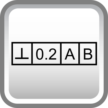
I think there is a mistake, in the Example the tolerance is 0.2 and the image below said that the gauge can not vary more than 30 microns.
Maybe you are taking the tolerance from the first image.
Yes that is correct – sorry for the confusion – the reference is for the previous drawing.
It is useful information to everyone.
Thank you so much GD and T Basics Team.
Hello, I have a question, what happens when we measure circular runout of a datum to itself as a datum? does the circular runout turn into circularity in this case? Our customer is insisting on changing circularity on our prints to circular runout on one feature where this feature is the main datum to the other features. This way they want to force us to measure circularity (or as they call it circular runout) in our automated gauge. Appreciate it if you could answer this.
Thanks a lot for this information. I am M.tech mechanical engineering student.
what is true profile symbol ?
Neeraj –
There is no symbol for true profile. The definition of a true profile is the theoretically perfect geometric shape shown on the drawing. There are two controls that you can use to dictate the tolerance for profile. Profile of a line and profile of a surface, both of these symbols are found on our symbols page. I hope this helps clarify things for you.
Cheers,
Matt
hi,
Runout is applied to both feature and feature of size.
what will be the virtual condition, if runout is applied to feature i.e. cylindrical surface? will it affect the worst case boundary or not, as in the case of starightness control?
what will be the virtual condition, if runout is applied to feature of size ? will it affect the worst case boundary like
starightness control?
I think you are confusing virtual condition with part envelope. The virtual condition is related to other features, the envelope is not (like the straightness callout) Size controls form no matter what (unless independedncy is called, or there is straightness/flatness applied to a feature of size) So with runout, the individual feature would still always need to be in its limit of size – I.e. the form can not allow the size to go out of tolerance.
Is total runnout to a and b correct when b is a perpendicular surface?
Gary –
Yes, using it in this application is a little bit unusual but allowed. The datum is essentially setting the axis that the face has to be perpendicular to. Then the tolerance zone is just two parallel planes that the entire surface has to be contained within in order to be considered ‘in spec’.
Hope this helps.
Cheers,
Matt
Hi there…
I am having a bit confusion regarding cylindricity, circularity and run-out…. I find all of them quite similar and am confused regarding their application….
Please guide me..
Suppose i have a cylinder with dia 120 with dimensional tolerance 0.5.
and I have applied a runout symbol to it with 0.2 tolerance.
what will be the max size of shaft that is aceptable.
It is 120+.5+.1=120.6 or 120.5
Gupta –
Careful here. Your cylinder still has to be within the limits of size, i.e. 120.5, at all cross sections in order to produce an acceptable part. Runout is a composite control as it measures form, orientation and location. I believe what you are really after is the virtual condition for your scenario. In this instance the maximum offset from the datum axis at the MMC condition would be the 120.5 as you state.
Hope this helps.
Matt
Need to difference between Runout & Concentricity & How to check
Manojkumar –
Big difference between two. I’d caution you against using concentricity, it is a difficult (and expensive) control to manufacture and inspect. It only has a specific few applications, otherwise it can be better represented using position or profile. Now, as to the difference:
Simply stated, runout is how much material is away from your datum axis (within the limits of size)
Concentricity is taken from a simultaneous two point measurement (where the measurements are made directly opposite one another), the median points of the diameter must be within the circular tolerance zone (also within the limits of size)
Runout can be measured using a chuck or collet and a dial gage, pretty straightforward. Measuring concentricity isn’t so easy. If you don’t have a CMM you need some specialty equipment that goes beyond our guidance here. Plenty of information out there on Youtube and google.
Hope this helps.
Cheers,
Matt
I have two bearing bores and I want to align those two bores. Is it proper to call inner bore datum A, outer bore datum B and use True Position on bore B to Bore A?
We have drawings that call out Total Runout of bore A and bore B, Runout bore A and Bore B and Runout bore B to bore A.
First, the use of Total Runout to control the alignment of two axes is appropriate as runout also controls position among other things. However, depending on your application you may be adding unnecessary cost into your part. I’m not positive I fully visualize the exact part you are describing but you can use positional tolerancing as you describe or use composite positional tolerancing. I’d urge you to take a look at the ASME Y14.5-2009 standard as they have several good examples of your exact situation. In particular take a look at Section 7.5.3 and the associated figures.
Hope this helps!
Cheers,
Matt
Hi, I’ve a query on the Runout. Can a runout be specified to a cylindrical surface whose axis is specified in the runout control frame?
—————
—————
consider the above 2 lines (they are broken here because i’m not sure if i can attach any drawing here for understanding) as a cylinder and the diametrical dimension is specified to it and say datum A is mentioned to the feature’s dimension. Hence Datum A is the axis to the two lines. Can I give the runout control to one of the line say the top line (which is a cylindrical surface) with respect to the datum axis A?
Because I’ve this doubt after seeing the Fig 9-7 in ASME Y14.5-2009 where datum D is called as a secondary datum for the total runout of 0.05 on the same feature where the Datum axis D would be present.
Yes you are correct and this is one component of the standard that leads to more confusion than help. You can specify a datum as a secondary datum lets say “D” for example, and then make a runout call to itself using datum reference frame “CD” (C being the perpendicular face next to the cylindrical feature). You are establishing an a datum reference axis with the primary perpendicular datum “C” first and the surface ‘D” itself as the secondary. This creates an axis “CD” that is theoretically different from axis “D” which is the derived axis of the cylindrical feature. This is the same function as using a perpendicularity tolerance from the cylindrical axis “D” to the flat face “C”, and then including a circularity tolerance (or cylindrical if you are replacing total runout)
You could not set runout of datum “D” to datum “D” as you would essentially only be setting the circularity of the part (its axis location to itself can not vary, so you would only be measuring form)
Hope this help and sorry for the late answer!
Hi,
Both Dat um on surface of cylinder and Datum Axis of cylinder both are same or not, Please Reply
Hello – yes a datum on surface or on the dimension size is acceptable. However it is NOT acceptable to place the datum on the center line of a feature. (because then which feature is the datum?)
But does placing a run-out tolerance on the center of the dimension mean the same as on the surface? Since the run-out of the axis is something different than the run-out of the surface. There is some misunderstanding about this in our company. ISO 1101 and other examples on the internet are not conclusive…
Typically you always want to show runout on a specific feature and never an axis. Many features can share an axis so you need to make it clear which feature you are controlling – especially for runout.
GD&T Questions
It is usually necessary to control datum features on the drawing in order to control
a. Runout, Orientation and Form
b. Runout, Orientation and Location
c. Form,Orientation and Location
d. Runout, Form and Location
Runout is the controlling of an
a. surface b.axis c.Centerplane D. Axis or surface
With Runout, when the geometric tolerance is smaller than the size tolerance of a feature, runout controls
a. Only form of the surface
b. only coaxiality and form of the surface
c. The form, Orientation and coaxiality of the surface
d. c. The form, Orientation and coaxiality of the axis
Correct answer please
I’m sorry – We aren’t going to answer homework questions on here.
Hi GDandT Basics! I’ve searched for long time a GD&T multilingual glossary for Standard words in GD&T. Would be great if you could help me, I’m working in Nikon Metrology UK, in the localisation area and we have the software translated to 10 languages, we need to check the consistency of the technical glossaries.
Thank you in advance.
Regards, Teresa
I wish I could help but I am uni-lingual and only know some enough Spanish to order food and find the bathroom. Sorry!
We are looking for an alternative to the Mersen CL-Profiler model CLP01 for roughness nad roundness measuring.
See http://eaindiainfo.com/pdf/cl_profiler.pdf
Do you have any?
At our old plant we used a Mahr digital measurement probe for any surface reading that could be combined with a precision spindle for runout. From what I remember it was a Mahrsurf XC. I was not in the metrology department but we used these quite often. I think they are quite expensive though
Sir,
1) i had understood all basic concept of GD and T. But I want to how to measure a cylindricity, runout and total runout.
2) I need some basic of MMC, LMC and bonus tolerance with some easy example.
good job done gdandt team..!!!!
Thanks for the feedback! Glad to help.
I am having a hard time convincing people that the Datum callout must be on a Feature of size and not on the axis line of the part. A shaft could have many “axis” and cylinders that act independently until the run out datum axis is established on a FOS and the runout controls applied. Our Quality Dept. checks the journals of the ballscrews we manufacture as you show with the V-block, but interpret this as from the surface not to the axis. We are starting to manufacture a new product and they want to control it by center drills at each end applying the datum from a centerline.
The main question to ask yourself when trying to determine datum position and GD&T is how the part will function in the design itself. I am not sure how the journal is mounted or positioned for how it needs to function, but it probably needs to be assembled by a connection to a tangible feature, being a surface or feature of size somewhere.
Manufacturing can make the part any way they see fit as long as it meets the print. In fact some facilities use raw part “manufacturing test instructions” that give the controls based on the axis alone. That being said, on your final print, GD&T is about design function first. Quality should be inspecting the part based on its final function, not how the part is manufactured.
Runout can also be called between two datums which in a way would set up a sort of virtual axis on the part between these features. You would call one datum A and one datum B and the datum in the feature control frame would be labeled “A-B” This still would be measured using V-Blocks though.
Whenever you are determining datum position, just think about the part’s real world function.
Thanks for the great question!
Runout can also be constrained using a face as well as another circular surface. If this is the case the perpendicularity of the datum face to the reference surface can add into the runout of the surface as well, since if the part is tilted at an angle, the part would runout higher due to the tilting of the part.
please explain this
Please let me know the difference between runout and circularity.
or total runout and cylindricity
Its all about datums. Circularity is a form control that holds a part to a circular shape, without relating it to the size or any other feature. Runout also is not dependent on the size of the part, but it controls the form of a part as it is rotated, while controlling another datum feature.
You can also view runout as a combination of ciruclarity (how round the individual feature is) and its concentricity (how aligned the center axis of the part is to a datum)
Total runout and cylindricity are the 3D versions of these two concepts. While a cross section of a part needs to be held in tolerance for circularity and runout, and entire features surface must be in tolerance for total runout and cylindricity. For that reason, total runout and cylindricity are hard to measure and control and should only be used in high precision applications like engine bearings.
Thanks for the nice feedback!
Circularity is independent (The deviation from an ideal circle of dia n). But runout should be always with respect to some other datum.
runout and total runout are datum referenced while circularity and cylindricity do not need reference from datums.